Thinning consists of deleting some points from an object while preserving its topology. In other words, thinning allows to reduce the amount of information in a shape while preserving some of its characteristics (such as the number of pieces, cavities, tunnels, ...). A skeleton is a result of a thinning process that:
In addition, in some applications, the skeleton should also contain geometrical information about the object it was computed from (the skeleton should "look like" the original object).


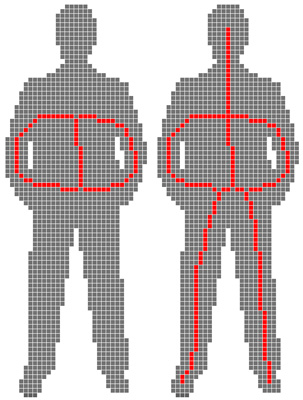
Two strategies exist in order to obtain a skeleton "visually close" to the original shape, and both are based on selecting points which should not be removed during thinning:

Click here to see full size image (1394x725)
In conclusion, we can say that if one does not want to give any parameter (any clue on the shape) to the thinning algorithm, he or she will obtain a skeleton with spurious elements. Moreover, it is difficult to prove that a thinning algorithm produces a thin result in the voxel framework.
The lambda-medial axis was originally proposed in the continuous framework by Chazal & Lieutier, who proved its stability to noise and rotation.
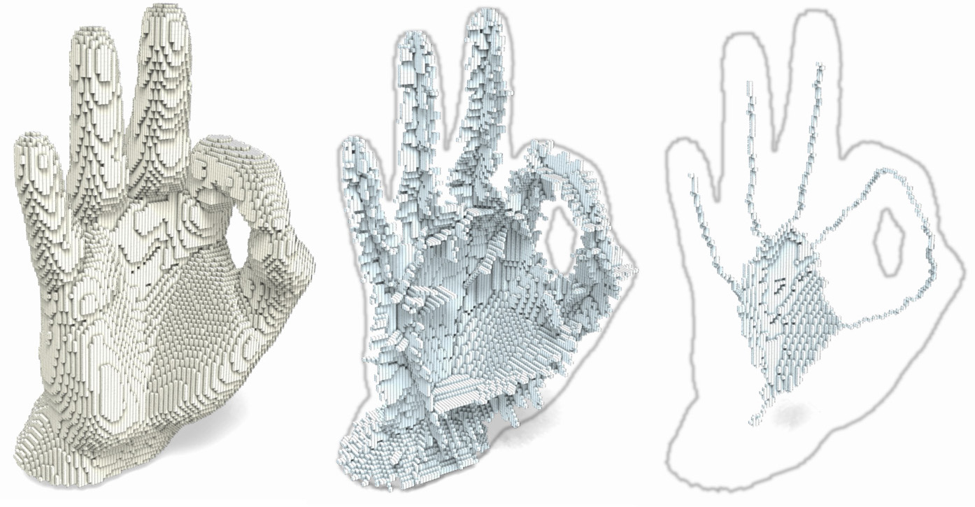
The Euclidean medial axis consists of mapping to each point x of an object the radius of the maximal ball centered on x (the point is given the value 0 if it is not a center of maximal ball). The lambda-medial axis consists of mapping to each point x of an object the radius of the smallest point containing E(x), where E(x) is the set of points of the complementary of the object which are the closest to x.

We adapted, in [ChauCouTa2010], the lambda-medial axis to the discrete framework and studied how it could be used in order to obtain a skeleton "looking like" the original object (more details on thinning were given in [Chaussard_phd]). We also proposed a method for comparing medial axes, and compared the lambda-medial axis with the well-known Euclidean medial axis and with the integer-medial axis (Hesselink & Roerdink). We showed that the lambda-medial axis is more stable to noise and to rotation.

Click here to see full size image (1739x1461)
The lambda-medial axis is therefore a very good tool for choosing a set of points to preserve during thinning. The source code of this program should be soon available for download on this web site.
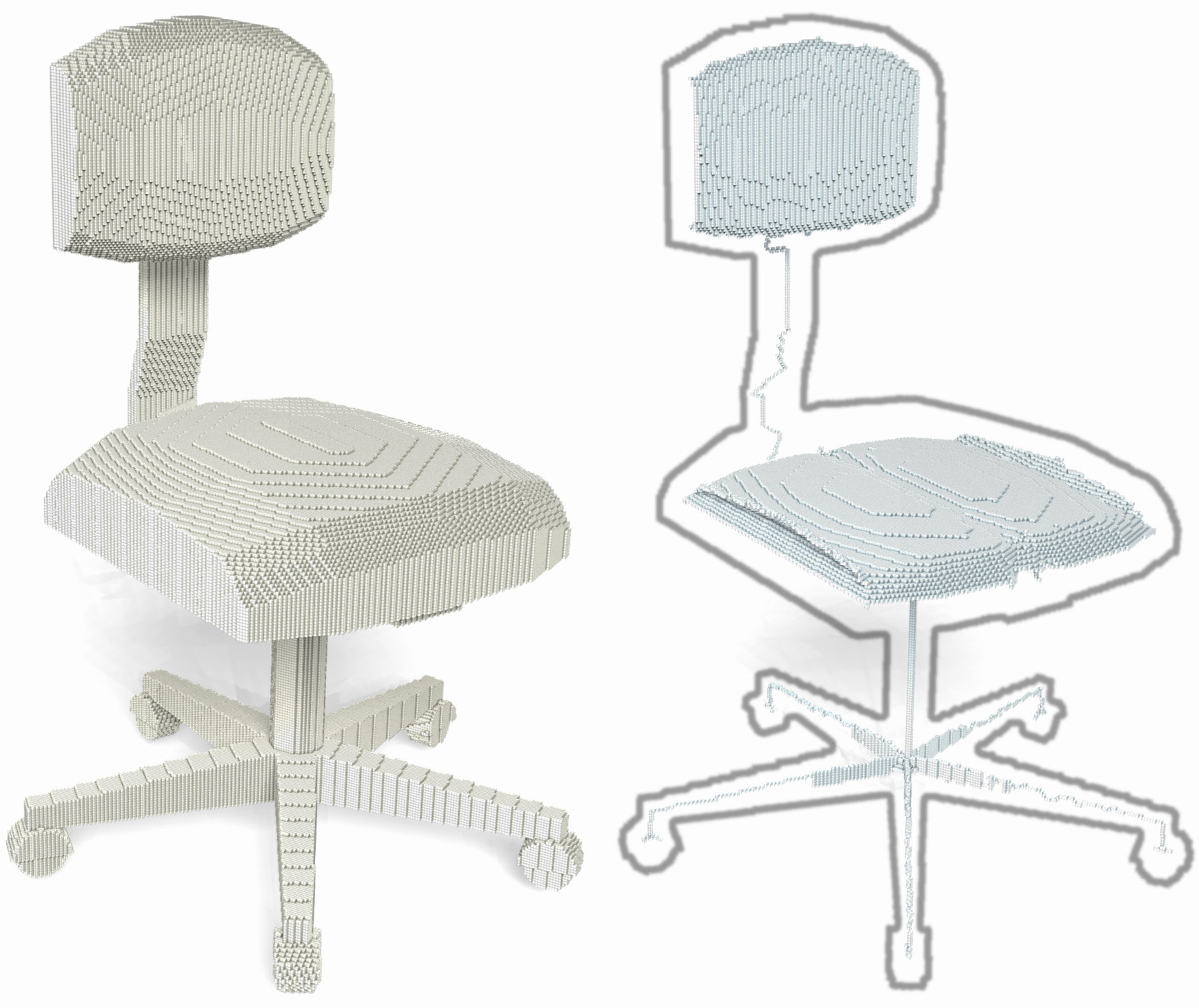
In the cubical complexes framework, a discrete object is not made of voxels, but of cubes, squares, edges and vertices. In this framework, topology is well defined on the whole space, definitions are generally valid in every dimensions and strong links with the continuous framework were established. Practically speaking, using cubical complexes allows to solve easily some hard problems of the voxel framework, such as parallel thinning, decomposition of a skeleton into simple elements, or giving a definition of thinness in every dimension.
We proposed a parallel thinning algorithm [ChauCou2009] in the cubical complexes, and we proved that this algorithm produces thin results. In order to obtain thin skeletons "looking like" the original input, we gave a general scheme for using this algorithm with any medial axis defined in the voxel framework.
We also proposed [Chaussard_phd] in this framework a new user-free thinning (no need of any input from the user) for obtaining skeletons "looking like" the original input and containing very little spurious elements. We compared this method with other user-free thinning algorithms (in the voxel framework), and we showed that our method has, in average, the best visual results and the best stability to noise and rotation. Moreover, we proved that the results of this algorithm are thin.


Thanks to this framework, it is very easy to decompose a skeleton into curves and surfaces. We are currently working on propagation of the skeleton's labels into the original volume: after a skeleton has been decomposed and all its parts have been labeled, we can propagate these labels inside the original object in order to label all its points and obtain a decomposition of the volume. The source code of this program should be soon available for download on this web site.

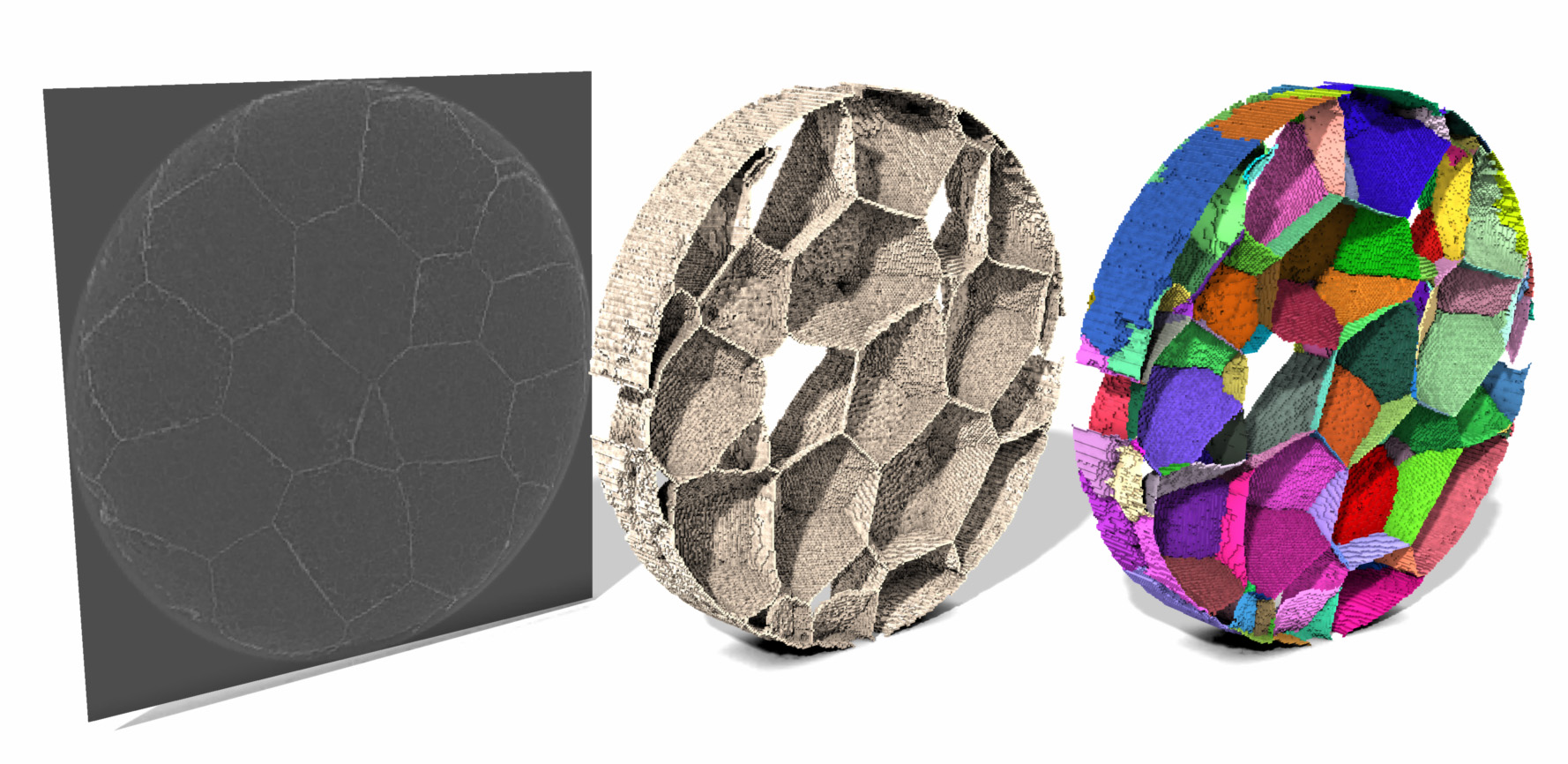
Click here to see full size image (1778x866)

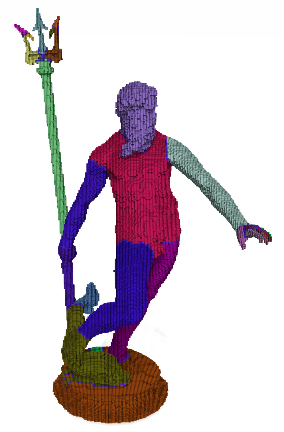
Click here to see full size image (996x1513)
This work was done during the first year of my thesis, and is part of another research theme: there are little connections with the work previously explained. This work is published in [ChauBerCou2010].
When one simulates a fluid flow through the pore space of a material, he or she will realize that the paths followed by the fluid looks like the skeleton of the pore space of the material. The goal of this work was to study how the skeleton of the pore space of a material be used in order to speed up fluid flow simulation calculation.
Our initial idea was to obtain a curvilinear skeleton that could then be easily transformed into a graph where the fluid flow could then be simulated using a max flow algorithm (Ford and Fulkerson, Tarjan and Goldberg, ...). In order to avoid surface patches in the skeleton, it is necessary to remove the grains of the material (pieces of the material which are not connected with the borders of the image). However, the material is considered to be embedded in a toric space: if some fluid leaves the material by one side, it will come back inside the material by the opposite side. In this situation, all the parts of the material which do not wrap around the toric space will also create surface patches in the skeleton: we call these toric grains.
Unlike classical grains, toric grains cannot be characterized in terms of image border. However, we found out a interesting characterization based on topology: an element of the material is not a toric grain iff it contains a loop which cannot be reduced (by continuous deformation) to a single point. We proposed a new definition of loops and continuous deformation adapted to the toric space, and we found an easy way to characterize such loops. Finally, we proposed a linear time algorithm allowing to detect toric grains in an object.

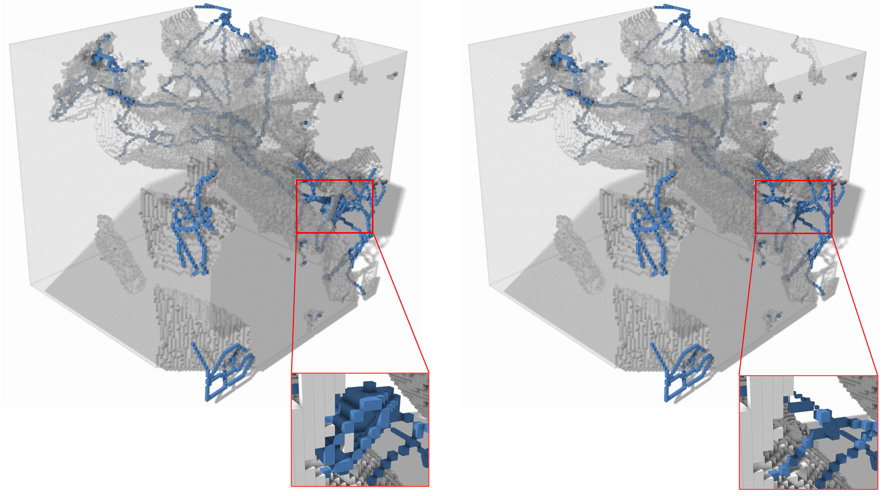
Click here to see full size image (1758x985)
This algorithm can be used to remove toric grains from the image of a material and enhance the chances of obtaining a curvilinear skeleton of the pore space.